
-20%
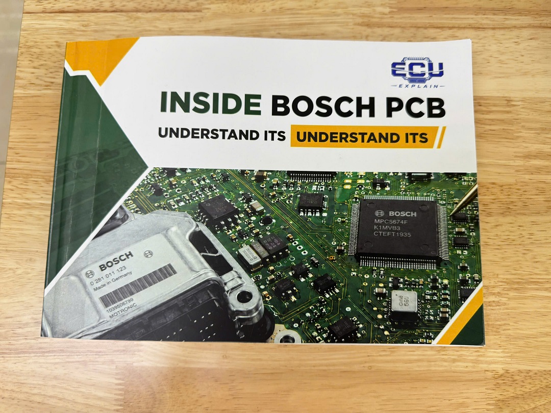
PCB ECU Component Functions: Understand the Role of Every ECU Component
Original price was: 249 $.199 $Current price is: 199 $.
- Comprehensive ECU PCB Component Analysis Covers:
- MCU, Flash Memory & EEPROM Functions
- Voltage Regulators & Switching Power Supplies
- Driver ICs & Power Transistors
- Protection Diodes & Circuit Components
- CAN Transceivers & Communication Interfaces
- Component Interaction Across Major Bosch ECU Families
- Written for automotive technicians, ECU repair specialists, engineers & technical learners
- Practical component-focused reference for ECU diagnostics and repair
- Technical support included after purchase
Sales Information
- Policy: Support during your studies
- Warranty: 12 Month
- Payment method: Payment via PayPal
- Transport: Worldwide shipping
- Technical Support: Support for software installation and usage
Gift included:
- Private technical support group with at least 3 technicians
- Protective Carrying Box
- Free database for coding and programming
- Free trial of electrical wiring diagram software
- Support during your studies
Modern automotive ECUs contain many electronic components working together as one control system. Each component has a specific role in processing signals, managing power, storing data, protecting circuits, or controlling communication.
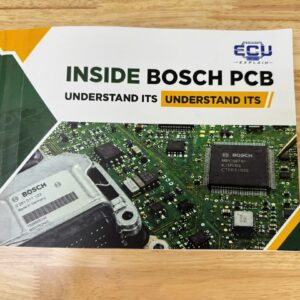
PCB ECU Component Functions is a technical reference designed to help readers understand what individual electronic components do inside automotive ECU circuit boards.
The book focuses on component identification, functional analysis, and interaction between components. It uses practical examples from Bosch ECU families used across passenger cars, commercial vehicles, European platforms, and Asian applications.
What Is PCB ECU Component Functions?
PCB ECU Component Functions explains the practical role of electronic components found on automotive ECU PCBs.
The book helps readers connect a physical component with its function inside an ECU circuit.
The main focus includes:
- Microcontrollers (MCUs).
- Flash memory.
- EEPROM.
- Switching power supplies.
- Voltage regulators.
- Driver ICs.
- Power transistors.
- Protection diodes.
- CAN transceivers.
- Communication interfaces.
- Other supporting electronic components.
The book does not focus on ECU pinout information. Instead, it explains what components do and how they interact within ECU circuit sections.
Why Is Understanding ECU Component Functions Important?
Understanding component functions helps technicians interpret ECU hardware more accurately.
A PCB contains many components with different electrical roles. Identifying a component is only the first step.
A technician also needs to understand:
- What the component does.
- Which circuit section it belongs to.
- What type of function it performs.
- How it interacts with nearby components.
- How it contributes to ECU operation.
This knowledge can support a more structured approach to ECU diagnostics and repair.
Which ECU Components Does the Book Explain?
The book focuses on the core electronic components commonly encountered during ECU PCB analysis.
Microcontroller Unit (MCU)
The MCU is the central processing component of an ECU.
It processes electronic information and executes the control logic required by the ECU system.
Within an ECU architecture, the MCU interacts with other components such as:
- Memory devices.
- Power supply circuits.
- Driver ICs.
- Communication circuits.
- Signal-processing sections.
Understanding the MCU helps readers recognize its position within the overall ECU architecture.
Flash Memory
Flash memory provides non-volatile data storage within an ECU.
It can retain stored information when ECU power is removed.
Within ECU architecture, Flash memory works alongside the MCU and other electronic circuits.
The book helps readers identify Flash-related components and understand their functional role within different Bosch ECU designs.
EEPROM
EEPROM is a non-volatile memory technology used for storing ECU data.
Unlike temporary working memory, EEPROM can retain information without continuous power.
Its role depends on the ECU architecture and the specific system being analyzed.
The book includes EEPROM as one of the important memory components encountered during ECU PCB analysis.
Switching Power Supplies
Switching power supplies manage electrical power through controlled switching operations.
An ECU requires suitable power conditions for its electronic circuits.
Power supply sections can therefore include multiple components working together to manage and distribute electrical energy.
The book examines switching power supply structures as part of ECU component analysis.
Voltage Regulators
Voltage regulators provide controlled voltage levels for ECU electronic circuits.
Different components may require specific electrical supply conditions.
Voltage regulation helps create the appropriate supply environment for components such as:
- MCUs.
- Memory devices.
- Driver ICs.
- Communication circuits.
The exact implementation varies between ECU designs.
Driver ICs
Driver ICs connect control logic with circuits that require controlled electrical operation.
They can be used to control different loads or output stages within an ECU.
Driver ICs may work together with power transistors and other supporting components.
Understanding their function helps explain how ECU processing logic can interact with external vehicle systems.
Power Transistors
Power transistors handle controlled electrical switching or power delivery within ECU circuits.
They can form part of actuator or power-control sections.
Their exact function depends on the circuit design and application.
The book includes power transistors among the components that technicians may encounter when examining ECU PCBs.
Protection Diodes
Protection diodes help protect electronic circuits from unwanted electrical conditions.
They can form part of protection sections around sensitive ECU electronics.
Protection components are particularly relevant because automotive ECUs operate in electrically demanding environments.
The book considers protection diodes as part of the functional analysis of ECU PCB components.
CAN Transceivers
A CAN transceiver provides the electrical interface between ECU communication logic and the CAN network.
It works between the ECU’s internal communication circuitry and the physical communication network.
This makes the CAN transceiver an important component in ECU communication architecture.
Understanding its role helps technicians distinguish communication-interface components from processing and power components.
Communication Interfaces
Communication interfaces allow ECU electronics to exchange information with other vehicle systems.
Modern vehicles use multiple electronic control units that must communicate with each other.
An ECU therefore contains dedicated circuits that support communication functions.
The book introduces communication interfaces as part of the broader ECU component architecture.
How Do ECU Components Work Together?
ECU components operate as interconnected circuit sections rather than isolated parts.
A simplified ECU architecture can be viewed as several functional blocks:
- Power section – manages electrical supply.
- Processing section – executes control logic.
- Memory section – stores required data.
- Driver section – controls electrical outputs.
- Protection section – supports circuit protection.
- Communication section – handles data exchange.
These sections depend on each other.
For example, the MCU requires suitable power and memory support. Communication circuits require processing logic, while driver circuits can depend on control signals generated by the MCU.
This interaction is a central concept throughout the book.
Which Bosch ECUs Are Covered?
The book uses a broad range of Bosch ECU families as practical reference examples.
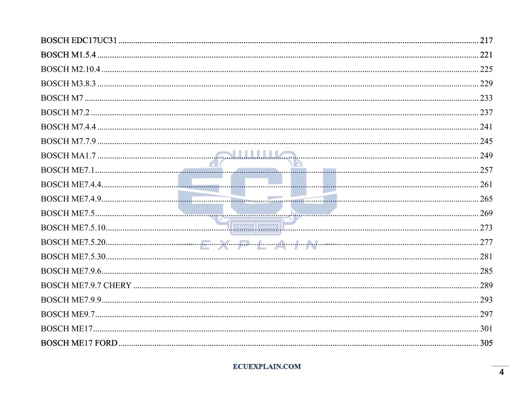
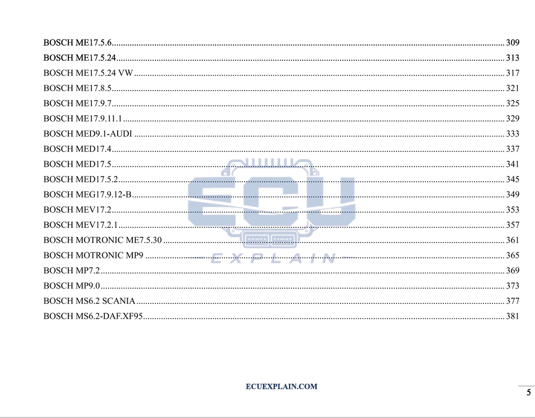
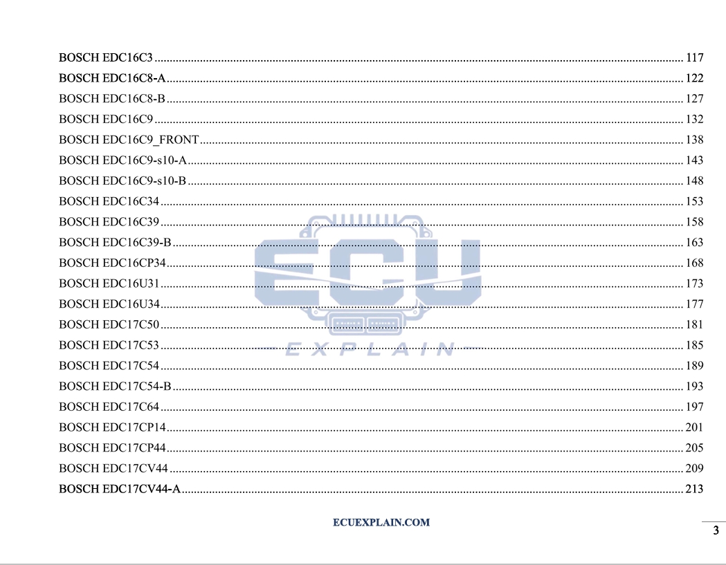
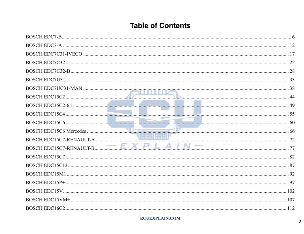
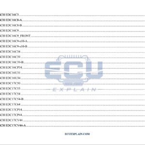
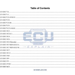
The table of contents includes numerous ECU generations and platforms.
Bosch EDC Families
The book covers examples including:
- EDC7-B.
- EDC7-A.
- EDC7C31-Iveco.
- EDC7C32.
- EDC7U31.
- EDC7UC31-MAN.
- EDC15C2.
- EDC15C4.
- EDC15C6.
- EDC15C7.
- EDC15C13.
- EDC15M1.
- EDC15P+.
- EDC15V.
- EDC16C2.
- EDC16C3.
- EDC16C8.
- EDC16C9.
- EDC16C34.
- EDC16C39.
- EDC16CP34.
- EDC16U31.
- EDC16U34.
- EDC17C50.
- EDC17C53.
- EDC17C54.
- EDC17C64.
- EDC17CP14.
- EDC17CP44.
- EDC17CV44.
- EDC17UC31.
These examples cover different Bosch diesel ECU generations and applications listed in the book.
Which Bosch Gasoline ECUs Are Included?
The book also includes a wide range of Bosch gasoline ECU families.
Examples include:
- M1.5.4.
- M2.10.4.
- M3.8.3.
- M7.
- M7.2.
- M7.4.4.
- M7.7.9.
- MA1.7.
- ME7.1.
- ME7.4.4.
- ME7.4.9.
- ME7.5.
- ME7.5.10.
- ME7.5.20.
- ME7.5.30.
- ME7.9.6.
- ME7.9.7.
- ME7.9.9.
- ME9.7.
- ME17.
- ME17.5.6.
- ME17.5.24.
- ME17.8.5.
- ME17.9.7.
- ME17.9.11.1.
- MED9.1.
- MED17.4.
- MED17.5.
- MED17.5.2.
- MEG17.9.12-B.
- MEV17.2.
- MEV17.2.1.
- Motronic ME7.5.30.
- Motronic MP9.
- MP7.2.
- MP9.0.
The book also includes specific examples associated with platforms such as Ford, VW, Audi, Chery, Scania, DAF, Iveco, MAN, Mercedes, and Renault, as listed in the table of contents.
How Is Each Component Analyzed?
Each chapter uses a practical approach to connect component identification with functional understanding.
The book is structured around three main areas:
1. Component Identification
Readers learn to recognize electronic components located on ECU PCBs.
Identification provides the foundation for understanding the circuit.
2. Functional Analysis
The next step is understanding what each component does.
The focus is on the component’s role within its ECU circuit section.
3. Component Interaction
Components do not operate independently.
The book examines how different components work together within the ECU architecture.
This approach helps connect individual components with the broader function of the control unit.
Who Is This ECU Component Manual For?
The book is intended for professionals and learners who want a stronger understanding of automotive ECU electronics.
It can be useful for:
- Automotive electronics technicians.
- ECU repair specialists.
- ECU diagnostic technicians.
- Automotive mechatronics students.
- Automotive engineers.
- ECU hardware specialists.
- Technical learners studying engine management systems.
It is particularly useful for readers who want to understand the function of ECU components, rather than only identifying ECU models.
What Will You Learn?
The book develops a component-focused understanding of automotive ECU circuit boards.
Key learning areas include:
- Identify common ECU PCB components.
- Understand MCU functions.
- Understand Flash memory functions.
- Understand EEPROM functions.
- Recognize voltage regulation circuits.
- Understand switching power supplies.
- Identify driver ICs.
- Understand power transistor functions.
- Recognize protection diodes.
- Understand CAN transceiver functions.
- Identify communication interface components.
- Understand interaction between ECU components.
- Compare component structures across different Bosch ECU families.
The goal is to help readers move from component identification to functional understanding.
PCB ECU Component Functions vs. Basic ECU Identification
Basic ECU identification focuses on recognizing the control unit, while this book focuses on the components inside it.
Instead of concentrating only on ECU model names or external identification, the material examines the electronic architecture behind the ECU.
The learning path can be summarized as:
Identify the Component → Understand Its Function → Understand Its Circuit Section → Understand Component Interaction
This provides a practical framework for studying ECU electronics at PCB level.
Frequently Asked Questions
What is PCB ECU Component Functions?
It is a technical reference focused on identifying and understanding the functions of electronic components found on automotive ECU PCBs.
Does the book include ECU pinouts?
No. The main focus is component identification, component functions, and interaction between components.
Does it explain MCU functions?
Yes. MCU architecture and functional roles are among the core topics.
Does it cover EEPROM and Flash?
Yes. Both EEPROM and Flash memory are included as important ECU memory components.
Does it cover CAN transceivers?
Yes. CAN transceivers and communication interfaces are included in the component analysis.
Which ECU families are included?
The book covers numerous Bosch EDC, ME, MED, MEV, M, MP, Motronic, and MS ECU families listed in its table of contents.
Who can use this book?
It is intended for automotive electronics technicians, ECU repair specialists, diagnostic technicians, engineers, students, and technical learners.
Understand ECU Components
PCB ECU Component Functions focuses on one essential question: what does each component do inside an ECU?
The book covers MCUs, Flash memory, EEPROM, switching power supplies, voltage regulators, driver ICs, power transistors, protection diodes, CAN transceivers, and communication interfaces.
It also provides practical examples across a broad selection of Bosch ECU families.
For technicians, engineers, students, and ECU specialists, the book provides a structured way to study ECU component identification, component functions, and interaction between circuit sections.
Explore PCB ECU Component Functions and build a clearer understanding of the electronic components behind modern automotive ECUs.
Related products

-13%

Original price was: 720 $.629 $Current price is: 629 $.
-25%

Original price was: 2.000 $.1.500 $Current price is: 1.500 $.
-38%
Original price was: 200 $.125 $Current price is: 125 $.
-17%
Original price was: 300 $.250 $Current price is: 250 $.
-13%

Original price was: 400 $.350 $Current price is: 350 $.
-17%
Original price was: 300 $.249 $Current price is: 249 $.